Comparison of Optical Aberrations
Optical aberrations are deviations from a perfect, mathematical model. It is important to note that they are not caused by any physical, optical, or mechanical flaws. Rather, they can be caused by the lens shape itself, or placement of optical elements within a system, due to the wave nature of light. Optical systems are typically designed using first order or paraxial optics in order to calculate image size and location. Paraxial optics does not take into account aberrations; it treats light as a ray, and therefore omits the wave phenomena that cause aberrations. For an introduction on optical aberrations, view Chromatic and Monochromatic Optical Aberrations.
After defining the different groups and types of chromatic and monochromatic optical aberrations, the difficult part becomes recognizing them in a system, either through computer analysis or real-world observation, and then correcting the system to reduce the aberrations. Typically, optical designers first put a system into optical system design software, such as Zemax® or Code V®, to check the performance and aberrations of the system. It is important to note that after an optical component is made, aberrations can be recognized by observing the output of the system.
Optically Identifying Aberrations
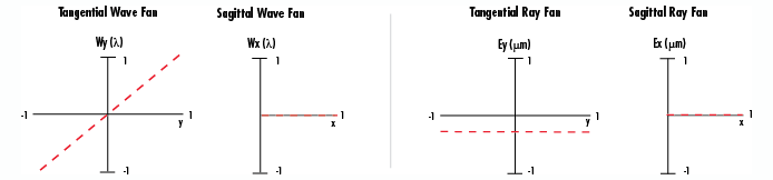
Determining what aberrations are present in an optical system is not always an easy task, even when in the computer analysis stage, as commonly two or more aberrations are present in any given system. Optical designers use a variety of tools to recognize aberrations and try to correct for them, often including computer generated spot diagrams, wave fan diagrams, and ray fan diagrams. Spot diagrams illustrate how a single point of light would appear after being imaged through the system. Wave fan diagrams are plots of the wavefront relative to the flattened wavefront where a perfect wave would be flat along the x direction. Ray fan diagrams are plots of points of the ray fan versus pupil coordinates. The following menu illustrates representative wave fan and ray fan diagrams for tangential (vertical, y direction) and sagittal (horizontal, z direction) planes where H = 1 for each of the following aberrations: tilt (W111), defocus (W020), spherical (W040), coma (W131), astigmatism (W222), field curvature (W220), and distortion (W311). Simply select the aberration of interest to see each illustration.
Aberration Name (Wavefront Coefficient):
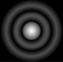
Recognizing aberrations, especially in the design stage, is the first step in correcting for them. Why does an optical designer want to correct for aberrations? The answer is to create a system that is diffraction limited, which is the best possible performance. Diffraction-limited systems have all aberrations contained within the Airy disk spot size, or the size of the diffraction pattern caused by a circular aperture (Figure 1).
Equation 1 can be used to calculate the Airy disk spot size (d) where λ is the wavelength used in the system and f/# is the f-number of the system.

OPTICAL ABERRATION EXAMPLES
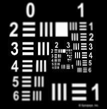
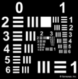
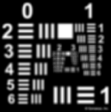
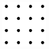
After a system is designed and manufactured, aberrations can be observed by imaging a point source, such as a laser, through the system to see how the single point appears on the image plane. Multiple aberrations can be present, but in general, the more similar the image looks to a spot, the fewer the aberrations; this is regardless of size, as the spot could be magnified by the system. The following seven examples illustrate the ray behavior if the corresponding aberration was the only one in the system, simulations of aberrated images using common test targets (Figures 2 - 4), and possible corrective actions to minimize the aberration.
Simulations were created in Code V® and are exaggerated to better illustrate the induced aberration. It is important to note that the only aberrations discussed are first and third orders, due to their commonality, as correction of higher order aberrations becomes very complex for the slight improvement in image quality.
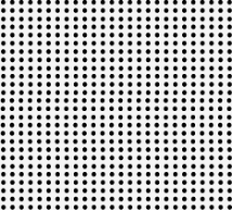
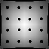
Figure 2: Fixed Frequency Grid Distortion Target
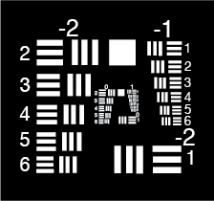
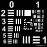
Figure 3: Negative Contrast 1951 USAF Resolution Target
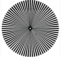
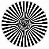
Figure 4: Star Target
Tilt – W111 |
|
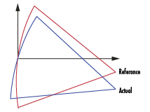
Figure : Representation of Tilt Aberration |
Figure 5b: Simulation of Tilt Aberration |
Characterization Image Has Incorrect Magnification Caused by Actual Wavefront Being Tilted Relative to Reference Wavefront First Order: W111 = Hρcos (θ) | Corrective Action Change System Magnification |
Defocus – W020 |
|
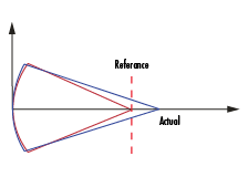
Figure 6a: Representation of Defocus Aberration |
Figure 6b: Simulation of Defocus Aberration |
Characterization Image in Incorrect Image Plane Caused by Wrong Reference Image Used to Correct for Other Aberrations First Order: W020 = ρ2 | Corrective Action Refocus System, Find New Reference Image |
Spherical – W040 |
|
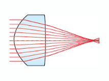
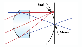
Figure 7a: Representation of Spherical Aberration |
Figure 7b: Simulation of Spherical Aberration |
Characterization Image Appears Blurred, Rays from Edge Focus at Different Point than Rays from Center Occurs with all Spherical Optics On-Axis and Off-Axis Aberration Third Order: W040 = ρ4 | Corrective Action Counteract with Defocus Use Aspheric Lenses Lens Splitting Use Shape Factor of 1:PCX Lens High Index |
Coma – W131 |
|
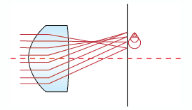
Figure 8a: Representation of Coma Aberration |
Figure 8b: Simulation of Coma Aberration |
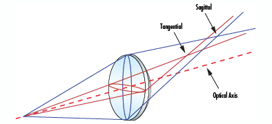
Characterization Occurs When Magnification Changes with Respect to Location on the Image Two Types: Tangential (Vertical, Y Direction) and Sagittal (Horizontal, X Direction) Off-Axis Only Third Order: W131 = Hρ3;cos(θ) | Corrective Action Use Spaced Doublet Lens with S in Center |
Astigmatism – W222 |
|
Figure 9a: Representation of Astigmatism Aberration |
Figure 9b: Simulation of Astigmatism Aberration |
Characterization Causes Two Focus Points: One in the Horizontal (Sagittal) and the Other in the Vertical (Tangential) Direction Exit Pupil Appears Elliptical Off-Axis, Radius is Smaller in One direction Off-Axis Only Third Order: W222 = H2ρ2cos2(θ) | Corrective Action Counteract with Defocus Use Spaced Doublet Lens with S in Center |
Field Curvature – W220 |
|
Figure 10a: Representation of Field Curvature Aberration |
Figure 10b: Simulation of Field Curvature Aberrationn |
Characterization Image is Perfect, but Only on Curved Image Plane Caused by Power Distribution of Optic Off-Axis Only Third Order: W220 = H2 ρ2 | Corrective Action Use Spaced Doublet Lens |
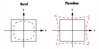
Distortion – W311 |
|
Figure 11a: Representation of Distortion Aberration
|
Figure 11b: Simulation of Barrel Distortion Aberration
Figure 11c: Simulation of Pincushion Distortion Aberration |
Characterization Quadratic Magnification Error, Points on Image Are Either Too Close or Too Far from the Center Positive Distortion is Called Barrel Distortion, Negative Called Pincushion Distortion Off-Axis Only Third Order: W311 = H3ρcos(θ) | Corrective Action Decreased by Placing Aperture S in the Center of the System |
Recognizing optical aberrations is very important in correcting for them in an optical system, as the goal is to get the system to be diffraction limited. Optical and imaging systems can contain multiple combinations of aberrations, which can be classified as either chromatic or monochromatic. Correcting aberrations is best done in the design stage, where steps such as moving the aperture s or changing the type of optical lens can drastically reduce the number and severity (or magnitude) of aberrations. Overall, optical designers work to reduce first and third order aberrations primarily because reducing higher order aberrations adds significant complexity with only a slight improvement in image quality.
版權所有 © 2026 江陰韻翔光電技術有限公司 備案號:蘇ICP備16003332號-1 技術支持:化工儀器網 管理登陸 GoogleSitemap